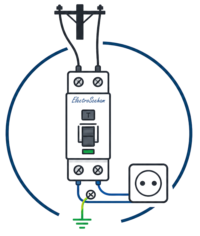
How an MCB miniature circuit breaker works
An MCB (Miniature Circuit Breaker) is the most common protective device in a domestic consumer unit. It protects the circuit against overloads and short circuits, but it does not detect small earth fault currents (residual currents in the milliamp range). On a bolted line-to-PE fault in a TN system it is the MCB itself that disconnects the circuit, provided the fault loop impedance is low enough (Zs·Ia ≤ U0, I7-2011 Art. 4.1.4.1.10). Here is what happens inside when it trips.
The internal components
A standard MCB contains five functional systems working together:
- The terminals — screws or clamps that secure the conductors
- The bimetallic strip — two welded metals (usually copper and steel) with different thermal expansion coefficients, which bends when heated
- The electromagnetic coil — a winding carrying the circuit current, with a moving core
- The trip mechanism — a spring-loaded lever that holds or releases the contacts
- The arc-extinction chamber — a stack of steel plates that fragments and cools the electric arc when the contacts open
1. Thermal protection — overload
When the current exceeds the rated value In marked on the MCB, the bimetallic strip starts to heat up. Because the two metals expand differently, the strip bends gradually. At sufficient deflection it releases the trip lever and the contacts open.
The thermal mechanism has an inverse-time characteristic relative to the overload: at 1.5×In it may take a few minutes, at 5×In a few seconds. IEC 60898-1 requires that the MCB must not trip in less than 1 hour at 1.13×In (the hold current), but must trip in less than 1 hour at 1.45×In.
2. Magnetic protection — short circuit
In a short circuit, the current rises sharply to values tens or hundreds of times In. The electromagnetic coil instantly generates a strong magnetic field that pulls in the moving core. This acts directly on the trip mechanism, opening the contacts in less than 10 milliseconds.
The magnetic trip current threshold varies with the characteristic (tripping curve) of the MCB:
| Curve | Magnetic threshold | Typical applications |
|---|---|---|
| B | 3–5 × In | Resistive circuits, lighting, long cables |
| C | 5–10 × In | Socket-outlets, general domestic use |
| D | 10–20 × In | Motors, transformers, discharge lamps |
3. The arc-extinction chamber
When a live contact opens, an electric arc forms between the two contacts — a column of ionised plasma at thousands of degrees Celsius. If the arc is not quenched quickly, the contacts melt and the MCB becomes unusable or even dangerous.
The extinction chamber contains a stack of thin steel plates that:
- fragment the long arc into a series of short arcs
- rapidly cool the plasma, reducing its conductivity
- force de-ionisation of the gas between the contacts
All this happens within a few milliseconds. The hot gas leaves through the vents in the MCB housing into the enclosure, so the clearances the manufacturer specifies in front of the vents must be kept. The arc gas does not decide whether an enclosure can be sealed: IP54 or IP65 enclosures fitted with MCBs are standard products, and their sizing, including any ventilation, depends on the power the devices dissipate.
4. Breaking capacity (Icn)
The breaking capacity (in IEC 60898-1, the rated short-circuit capacity, Icn) is the maximum short-circuit current the MCB can interrupt without destroying itself. It is expressed in kA and must be greater than the prospective short-circuit current at the point of installation.
Typical values:
- 6 kA — standard for domestic installations (a long distance from the transformer)
- 10 kA — needed at the main board of an apartment block or when the board is close to the transformer
- 15–25 kA — industrial installations or at the origin of the installation
What an MCB does NOT do
The MCB does not detect small residual currents to earth (in the milliamp range). If a person touches the line conductor and the current passes through the human body to earth, the MCB will not trip (the current through the circuit is almost the same — the difference is too small to activate the thermal or magnetic mechanism: residual currents of tens or hundreds of milliamps, dangerous to a person, are negligible against the MCB thresholds). That is the job of an RCCB or an RCBO.
Reference standard
The reference standard for domestic MCBs is IEC 60898-1 (SR EN 60898-1 in Romania), which defines the B/C/D characteristics, the rated short-circuit capacity Icn (standard values 1.5 / 3 / 4.5 / 6 / 10 kA and higher, up to 25 kA) and the tripping times for overloads and short circuits.
The I7-2011 code refers to MCBs in the context of overcurrent protection (Ch. 4.3) and of protection selectivity (Art. 4.3.7.1): cascaded MCBs must be coordinated so that, on a fault, the one nearest the fault trips, not the one at the incomer.
ElectroSchema
In the visual consumer unit in ElectroSchema, the MCB is placed on the DIN rails with the chosen rated current and characteristic. The validation rule V44 automatically checks the selectivity between the MCB on the sub-main and those on the circuits: it warns you when the magnetic bands of the two overlap, and also when the bands are separate but the prospective Icc at the busbars, entered on the board, exceeds the minimum magnetic threshold of the upstream MCB — above that current both can trip, so selectivity is only partial. Cascaded RCDs have their own rule, V29.
Discussion
Comments are moderated before publication. Your email is not displayed publicly.