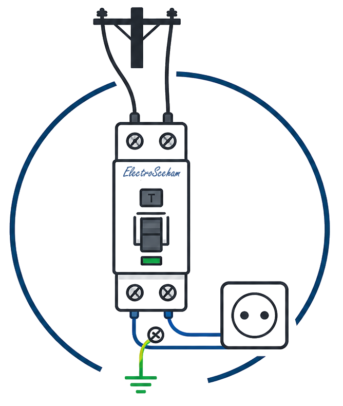
How an RCBO works
An RCBO (Residual Current Breaker with Overcurrent protection) combines the residual-current protection of an RCCB with the overcurrent protection of an MCB — usually in a single 17.5mm-wide module (some models take 2 modules). It is the practical choice for residential consumer units with limited space.
One device, three protections
If you have read the explanations for the MCB and the RCCB, you already understand 90% of the RCBO. It physically integrates both mechanisms: the toroid that detects the residual current and the bimetal/electromagnet that protects against overcurrent, both acting on a common tripping mechanism.
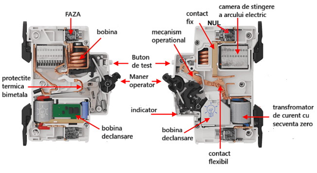
The internal components
Looking at an RCBO in cross-section, inside its body we find:
- The toroid — identical to the one in the RCCB, both conductors (L and N) pass through it
- The electronic detection relay — an amplifier sensitive to the flux imbalance
- The bimetallic strip — identical to the one in the MCB, for thermal protection
- The electromagnetic coil — for instantaneous magnetic protection against short circuits
- The common tripping mechanism — any signal from any protection opens the same set of contacts
- The arc-quenching chamber — the same as in the MCB
Miniaturisation is achievable because manufacturers have managed to reduce the toroid to less than 15mm in diameter while keeping the detection sensitivity at 30mA.
The RCCB section: the detection toroid
The operation of the toroid in an RCBO is identical to that of a standalone RCCB — both conductors (L and N) pass through the same core, and any imbalance generates a trip signal.
The MCB section: thermal and magnetic protection
The bimetallic strip and the electromagnetic coil are the same components as in a standard MCB. On overload, the bimetal bends slowly; on a short circuit, the coil trips instantly.
RCBO vs. RCCB + MCB: when to choose each
| Criterion | RCBO | RCCB + MCB |
|---|---|---|
| DIN modules | 1 module (17.5mm) | RCCB (2 modules, shared by the group) + 1 module per circuit |
| Selectivity with upstream RCD | The same: needs a type S RCD upstream, with IΔn ≥ 3× the downstream one | The same: needs a type S RCD upstream, with IΔn ≥ 3× the downstream one |
| Cost per circuit | Higher (25–40 EUR) | Lower: MCB + share of RCCB |
| Selective replacement | You replace the whole RCBO | You replace only the faulty MCB |
| Small board (<12 modules) | Ideal ✓ | Fits: N + 2 modules versus N with compact RCBOs |
| New installation, generous space | Acceptable | Recommended ✓ |
Selectivity with the upstream RCD
Selectivity against an RCD at the board incomer works the same way for an RCBO as for RCCB + MCB. The residual-current part of a general-type RCBO has the same tripping times as a general-type RCCB, 40...300 ms (Art. 4.1.5.2.7), so everything depends on the upstream device. In its 2011 wording, Art. 4.1.5.2.8 of I7-2011 put it by device type: selectivity between a type S device upstream and a general type downstream “may be considered achieved” if the ratio of their rated residual currents is at least 3. Since 2023 the article is a single sentence referring to Fig. 4.1/4.2 and to the recommendations of SR CEI 61200-53; the schemes in both figures keep the same ratio.
A general-type 100mA RCD at the incomer is not selective against a 30mA RCBO, even though the ratio is 100/30 ≈ 3.3: having no time delay, on a bolted fault it trips together with the RCBO. If the incoming RCCB is also 30mA (a frequent mistake), selectivity is impossible. The sum is exactly the same when the downstream device is a 30mA RCCB feeding a group of circuits. Where the two solutions really differ is between circuits: with RCBOs a fault takes out only its own circuit; with RCCB + MCB it takes out the whole group behind the RCCB. On 11 September 2026 we corrected this section: the first version claimed that the RCBO has poorer selectivity than RCCB + MCB, although the condition is the same for both.
The RCBO in the residential board — practical layout
A typical RCBO board layout:
Example 3-room flat board:
- → 1× RCCB 300mA type S — main protection, board incomer
- → 1× MCB 40A — main switch of the board; it can protect the feeder against overload (Art. 4.3.2.1.2), but the feeder’s short-circuit protection stays at its origin, in the meter cabinet
- → 1× RCBO 30mA / 16A C — living-room socket circuit
- → 1× AFDD+RCBO 30mA / 16A C — bedroom 1 socket circuit
- → 1× AFDD+RCBO 30mA / 16A C — bedroom 2 socket circuit
- → 1× AFDD+RCBO 30mA / 10A B — lighting circuit (it also feeds the bedrooms)
- → 1× RCBO 30mA / 20A C — washing-machine circuit (dedicated)
- → 1× RCBO 30mA / 20A C — boiler circuit (dedicated)
Total: around 12 modules (13 with a 2P MCB), because the AFDD usually adds one module per circuit; widths differ between manufacturers, so go for an 18-module board.
Since 2023 the AFDD has been mandatory on all AC circuits of no more than 32 A in the rooms fitted out for sleeping in residential buildings (Art. 4.2.2.10) and is installed at the origin of the circuit it protects (Art. 4.2.2.12) — either a combined AFDD+RCBO or an AFDD module assembled with the RCBO, as the manufacturer specifies. The example was corrected on 12 September 2026: in the first version the three circuits serving the bedrooms appeared without an AFDD.
Normative reference
The reference standard for the RCBO is IEC 61009-1 (SR EN 61009-1 in Romania). The difference from IEC 61008 (RCCB) lies in adding overload and short-circuit protection per IEC 60898-1. The I7-2011 standard accepts the RCBO as a functional equivalent of the RCCB+MCB combination.
ElectroSchema
In the ElectroSchema distribution board, the RCBO is configured with its rated current, characteristic (B/C/D), residual sensitivity and type (AC/A). At validation, rule V29 checks cascaded RCD selectivity: the residual current of the upstream RCD must be at least 3 times the downstream one and, as a practice margin of the app itself (not a requirement written in I7), at least two steps higher on the IEC scale — which is why 30mA → 100mA gets a warning while 30mA → 300mA, the combination of Fig. 4.2 referred to by Art. 4.1.5.2.8 of I7-2011, passes. It does not check whether the upstream RCD is type S; that choice is yours. Rule V05 checks that all sockets have residual-current protection ≤ 30mA (directly or through an upstream RCD).
Discussion
Comments are moderated before publication. Your email is not displayed publicly.