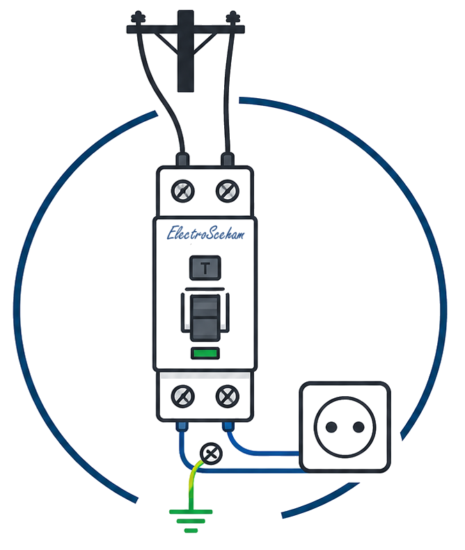
How an RCCB works
An RCCB (Residual Current Circuit Breaker) — also known as an RCD or residual-current device — is the device that protects people from electric shock. It works on a completely different principle from an MCB: it detects the difference between the current flowing into and out of the circuit.
The problem the RCCB solves
Currents of tens to hundreds of milliamperes — 30–100 mA is just 0.03–0.1 amperes — can be dangerous to a human, depending on how long they flow through the body. A 16A MCB has no way to sense a few tens of milliamperes on top of the circuit current, so it provides no additional protection against direct contact. In a TN system, however, when an insulation fault puts the line voltage on the enclosure of a class I appliance, the breaker does provide automatic disconnection of supply (Art. 4.1.4.1.11), provided the fault-loop impedance lets it trip within the time required by table 4.1.
According to medical data, current flowing through the human body for 1 second produces:
| Current | Physiological effect |
|---|---|
| 1 mA | Perception threshold — slight tingling |
| 10 mA | Muscle contraction — let-go impossible |
| 30 mA | Strong muscle contractions, breathing difficulties — below the fibrillation threshold (zone AC-3) |
| 100 mA | Ventricular fibrillation possible (zone AC-4) — life-threatening |
Source: IEC/TR 60479-1 — Effects of current on human beings and livestock. The values in the table are indicative, from the classic literature: IEC/TR 60479-1 takes 0.5 mA as the perception threshold (the limit of zone AC-1).
The working principle: the toroidal transformer
At the heart of an RCCB is a toroidal transformer — a ring-shaped ferromagnetic core through which both conductors pass: the line (L) and the neutral (N).
Under normal conditions, all the current entering on the line returns on the neutral: I_L = I_N. The two conductors generate equal and opposite magnetic fields that cancel out completely. The resulting flux in the core is zero.
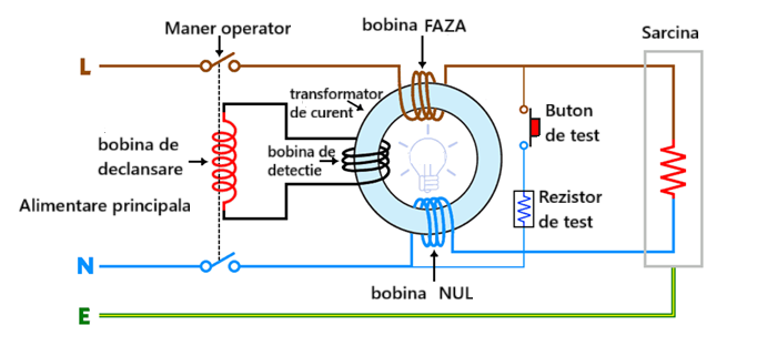
When an insulation fault occurs (or a person touches the line conductor), part of the current escapes directly to earth without returning through the neutral. Now I_L ≠ I_N. The difference — the residual current — generates a magnetic flux in the core that induces a voltage in the secondary winding. This energises a sensitive relay that mechanically trips the RCCB.
The standardised sensitivities
The I7-2011 standard requires 30 mA residual-current devices as a general rule for the protection of people on socket-outlet circuits and in bathrooms. To reduce the risk of fire, Art. 4.2.2.8 — in its 2023 form — recommends an RCD whose rated operating current is set according to the characteristics of the installation and which is placed in the distribution board; in practice 300 mA is chosen, usually type S, where tripping at 30 mA would be too sensitive. The “≤ 300 mA at the service entrance” threshold of the 2011 wording is no longer in the text in force.
Types AC, A, F, B — why they matter
Not all fault currents are sinusoidal. Modern electronic equipment (computers, chargers, inverters, EV stations) generates currents with DC or high-frequency components. A type AC RCCB does not detect these current waveforms.
The test button — what it checks and what it doesn’t
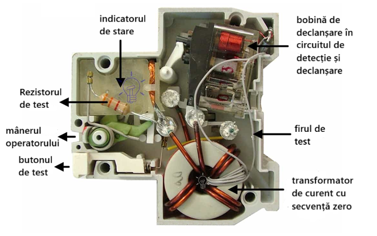
Every RCCB has a test button (T) that, through a test resistor, sends a current through the toroidal core on one conductor only, creating an artificial imbalance. Pressing it exercises the whole chain — core, secondary winding, relay, mechanism — but with a test current larger than IΔn, so it does not check:
- the tripping time at IΔn and at 5·IΔn
- the actual tripping current (it may trip at 50mA instead of 30mA)
- the continuity of the installation’s earth connection
Manufacturers recommend pressing the test button periodically; the interval is given in the device’s instructions. I7-2011 sets no frequency: at verification it requires the RCD to be tested, and the effectiveness of disconnection by the RCD is checked “using appropriate test equipment” (Art. 8.1.1.3.7). A full check (actual tripping current) requires a measuring instrument — an RCD tester. The first version of this article said the test button bypasses the toroidal core, pointed to Ch. 4.1.3.x for the 30 mA RCD requirement and presented RCCB–RCBO selectivity as secured by the 3:1 ratio; we corrected all three on 11 September 2026.
What an RCCB does NOT do
Normative reference
Reference standards: IEC 61008-1 / 61009-1 (RCCB/RCBO; types AC and A), IEC 62423 (types F and B), IEC/TR 60479-1 (effects of current on humans). The I7-2011 standard requires RCDs of at most 30 mA in Art. 4.1.5.2.1 (as amended in 2023) for general-use socket outlets and/or electrical loads with a rated current not exceeding 32 A, for mobile equipment for outdoor use with a rated current not exceeding 32 A and for lighting circuits in single-family dwellings, and in Art. 7.1.3.5 for every circuit in rooms with a bath or shower.
ElectroSchema
In the ElectroSchema distribution board, the RCCB is placed on the DIN rails with its sensitivity and type configured. The validation rules check that every socket outlet is protected by an RCD of at most 30 mA (V05), that a water heater in a bathroom with a bath or shower is not left on a plain MCB without a 30 mA RCD (V41), and flag RCD cascades whose ratio of rated residual currents is below 3:1 (rule V29). Real selectivity also needs a type S RCD upstream, as in the fig. 4.1 and fig. 4.2 schemes to which Art. 4.1.5.2.8 refers in its 2023 form.
Discussion
Comments are moderated before publication. Your email is not displayed publicly.