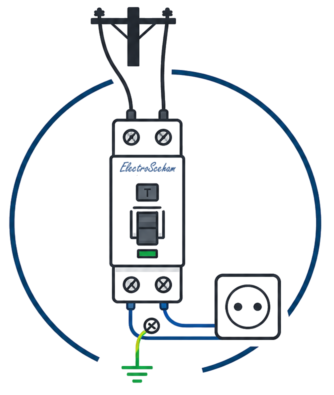
Protection by automatic disconnection: the principle and the disconnection condition
“I fitted a breaker, so I’m protected” — not quite. Fault protection doesn’t mean the breaker trips, it means it trips within the required time (0,4 s at a 230 V socket-outlet in TN). And whether you make that time depends on the fault-loop impedance — on the cables and on the PE — not on the breaker’s goodwill.
“I ran the cables, fitted the breakers, done — it’s protected.” It’s a trap even experienced electricians fall into. A breaker that trips on a fault but takes three seconds to do it at a 230 V socket-outlet has — on paper — tripped. In reality it didn’t meet the standard, and it left someone with a hand on a live enclosure for far too long. Protection by automatic disconnection isn’t judged by whether it trips, but by how fast.
Where it applies: the “fault” layer
This is the second half of protection against electric shock (I’ve written about the first — insulation and enclosures — separately). It comes into play the moment the insulation has failed and the metal enclosure of an appliance accidentally becomes live. Per Art. 4.1.4.1.1, automatic disconnection of supply is the most widely used protective measure in installations. The principle, from Art. 4.1.4.1.2, is straightforward: on a fault of negligible impedance between a line conductor and an exposed-conductive-part (or the PE), a device must automatically disconnect the supply within the maximum time laid down.
Translated to the site: if the line touches the enclosure, the fault current returns to the source through the protective conductor (PE). That current has to be large enough to force the protective device to trip before the touch voltage becomes dangerous for whoever puts a hand on the appliance.
A corollary many people forget: if the PE is broken somewhere along the run, the fault loop can no longer close, and the overcurrent protection may not trip at all — the enclosure stays live. That’s why continuity of the protective conductor isn’t a nicety; it’s the condition for this whole mechanism to work.
How fast: the 50 V benchmark and Table 4.1
Why maximum times, and not just “as fast as possible”? Because the standard’s benchmark is the conventional touch voltage limit, UL = 50 V a.c. — the value on which the maximum disconnection times are based (the note in Table 4.1 says so explicitly). Not that any contact below 50 V is “safe”, but that this is the standard’s reference threshold. From there: the higher the voltage to earth (U0), the higher the fault drives the touch voltage, so the permitted time goes down. The times in Table 4.1 apply to final circuits in buildings not exceeding 63 A where they have one or more socket-outlets, or 32 A where they supply only fixed-connected equipment (Art. 4.1.4.1.3, as amended by the 2023 updates) — that is, exactly the socket-outlets and lighting in a dwelling.
| System | 50 V<U0≤120 V | 120 V<U0≤230 V | 230 V<U0≤400 V | U0>400 V | ||||
|---|---|---|---|---|---|---|---|---|
| a.c. | d.c. | a.c. | d.c. | a.c. | d.c. | a.c. | d.c. | |
| TN | 0,8 | Note 1 | 0,4 | 1 | 0,2 | 0,4 | 0,1 | 0,1 |
| TT | 0,3 | Note 1 | 0,2 | 0,4 | 0,07 | 0,2 | 0,04 | 0,1 |
The band that concerns us directly is 120<U0≤230 V a.c. — the domestic 230 V network to earth: 0,4 s in TN, 0,2 s in TT. (Note 1 in the table: on d.c. 50–120 V, disconnection may be required for reasons other than shock. Note 2: if an RCD provides the disconnection, Art. 4.1.5.2 applies.) The table also offers a bit of relief: in TT, if an overcurrent protective device provides the disconnection and the equipotential bonding takes in all extraneous-conductive-parts, you may use the TN times. Corrected on 11 September 2026: the limit in Art. 4.1.4.1.3 and the d.c. cell of the TN row (1 s, not 5 s) now follow the 2023 updates (points 9 and 10); the a.c. columns are unchanged.
Why a good breaker may NOT protect you
This is where the opening point comes full circle. For disconnection to happen within the required time, fitting a breaker isn’t enough — the fault-loop impedance has to be small enough for the fault current to reach the tripping threshold. Art. 4.1.4.1.10 puts it as a formula, for TN systems:
- Zs — the fault-loop impedance: the source + the line conductor up to the fault point + the protective conductor from the fault back to the source (in ohms).
- Ia — the current that causes automatic tripping within the required time. Here’s a common confusion: on an MCB, Ia is not the rated current (16 A, 20 A), but the current at which it trips within the imposed time — and that depends on the curve. A Type C MCB’s magnetic band is 5–10× In, but when you check Zs·Ia ≤ U0 you take the upper end of the band, the only point where instantaneous tripping is guaranteed: 5·In for Type B, 10·In for C, 20·In for D. For a C16, Ia = 160 A, so Zs ≤ 230/160 = 1,44 Ω.
- U0 — the nominal voltage between line and earth (in volts).
In other words: if Zs rises, the fault current falls — and if it falls too far, a perfectly good breaker no longer trips within the required time. A loop that’s electrically too “long” (thin cable, long run, undersized PE) is exactly that.
That’s why conductor cross-sectional area, choice of protection and meeting the times in Table 4.1 are one and the same problem, not three separate decisions. “I fitted a 16 A MCB” says nothing if the fault loop is too large for the current, on a fault, to reach the fast (magnetic) tripping threshold within the required time.
One note, since the standard states it under the same Art. 4.1.4.1.10: if the protection is an RCD, Ia is the residual operating current — far smaller than an MCB’s threshold. Precisely because it’s small, an RCD “passes” the condition even with a high-impedance loop; its own proper verification, however, has its own rules, which I cover separately.
When it can’t be done in time
The standard doesn’t leave you hanging if you can’t make the time. Art. 4.1.4.1.7: if automatic disconnection can’t be achieved within the applicable time, a supplementary protective equipotential bonding connection must be provided — you don’t give up safety, you add a measure that keeps the touch voltage low.
Where ElectroSchema fits in
Of fault protection, the app checks the part it can “see” from the plan — the presence of residual-current protection where the standard requires it: V05 flags socket-outlets, and V18 lighting circuits without an RCD ≤ 30 mA upstream (Art. 4.1.5.2.1), while V07 requires IP44 in bathrooms. The condition Zs·Ia ≤ U0, by contrast, needs the actual loop impedance (site data), so it remains a design check and a measurement at commissioning — not something deducible from the drawing alone. That’s exactly why it’s worth thinking through from the start: cross-sectional areas and routes that keep Zs low, so the times in Table 4.1 are realistic, not just ticked off in the calculation.
Discussion
Comments are moderated before publication. Your email is not displayed publicly.