The protection relay: types and use in residential installations
MCB, RCCB, RCBO, AFDD — these are all protective devices with specific functions. Protection relays are a distinct category: as a rule they are not the protection of the conductors — that stays with the MCB or the fuse — but of the equipment and machinery, against dangerous operating conditions; the exception is the thermal relay with a contactor, which can even provide the overload protection of a motor circuit. Traditionally they appear less often in residential settings, in precise contexts where they are indispensable — yet the multifunction relay is increasingly making its way into residential circuits, as a single solution for monitoring the network parameters, complementing the protections required by the norm (MCB, RCD ≤ 30 mA, SPD), not replacing them.
What a relay is — the basic principle
An electric relay is an electromagnetically controlled switch: a small current (the control current) energises a coil that generates a magnetic field, which in turn moves a metal armature that opens or closes the contacts of a power circuit (high current).
The fundamental value of the relay is the galvanic isolation between the control circuit and the power circuit — a sensor at 12V DC can switch a 230V AC circuit with no direct electrical connection at all.
Modern relays come in many types: electromechanical (coil + physical armature), solid-state (with semiconductors) and numeric/digital (with a microprocessor). In residential applications, the most common are electromechanical relays and solid-state relays with a comparator.
1. The voltage relay (UV/OV relay)
The voltage relay monitors the mains voltage and disconnects the load when the voltage leaves a configurable band (typically ±10% of the 230V nominal, i.e. 207–253V per EN 50160).
What exactly it protects against:
- Undervoltage (brownout) — electric motors (pumps, AC compressors) overheat when running at reduced voltage: the current rises as 1/U, and the heat as I²
- Overvoltage — a sustained voltage above the normal band (above ~253 V) shortens the life of electronics and LED drivers, while large temporary overvoltages — for example towards ~400 V per phase when the neutral is broken — can destroy the equipment
- Voltage recovery after an outage — the relay has an adjustable reconnection delay: for compressor loads (air conditioning, refrigerator, heat pump) it is set to 3–5 minutes (180–300 s), so that the pressures in the refrigerant circuit can equalise, unless the appliance already has its own delay; a few seconds are enough only for loads without a compressor
2. The phase monitoring relay (three-phase)
For residential three-phase installations (pumps, large air-conditioning units, workshops), the phase monitoring relay simultaneously checks all three phases and trips at any anomaly that could damage the motors.
The most common failures it prevents:
- Phase loss — the most dangerous scenario: the three-phase motor tries to run on 2 phases, the current rises to 1.7–2× normal, the winding burns out within minutes
- Wrong sequence (phase reversal) — motors with a fixed direction (pumps, lifts, centrifugal fans) can break mechanically or flood if they run in reverse
- Voltage asymmetry — a 3–5% imbalance in voltages produces a 15–25% imbalance in currents (because of the motor’s low impedance), which overheats the winding
3. The thermal relay (motor overload)
The thermal relay is dedicated to protecting electric motors against prolonged overloads. Unlike the MCB, the thermal relay is adjustable (potentiometer) and has a time-current characteristic closer to the thermal behaviour of the protected motor.
It works on the same principle as the bimetal in the MCB, but sized for high currents and with fine adjustment. In residential settings it appears on:
- Pool or irrigation pumps (motors 0.5–2.2 kW)
- Motors for automatic gates and garage automation
- Industrial fans in workshops or greenhouses
- Air compressors for household use
| Relay type | What it monitors | Typical residential applications |
|---|---|---|
| Voltage relay | U_min / U_max single-phase | PV inverter, backup generator, submersible pump |
| Phase relay | Presence, sequence, asymmetry L1-L2-L3 | Three-phase motor, pool pump, large air conditioning |
| Thermal relay | Motor overload current | Irrigation pumps, automatic gate, compressor |
| Current relay | Loss of current (pump running without water) | Submersible pumps (dry-run protection) |
Relay vs. MCB — the essential difference
The MCB protects the conductors and the circuit — it trips when the current exceeds the thermal capacity of the cable. The protection relay protects the connected equipment — it trips when the equipment’s operating parameters (voltage, phase balance, temperature) leave the normal operating band.
A motor can run for years with a current below the MCB limit but with a slightly unbalanced voltage — and it will burn out gradually without the MCB sensing any problem. The protection relay does sense it.
The numeric/digital relay
Modern protection relays are in fact small microprocessors that measure the electrical parameters in real time and apply configurable algorithms. Compared with the electromechanical ones:
- Digitally configurable thresholds (not a potentiometer)
- They store the last N trips with timestamp and cause
- RS485/Modbus communication with automation and home automation systems
- Multiple functions in the same body (voltage + phases + frequency + power)
The multifunction relay — one module, all the protections
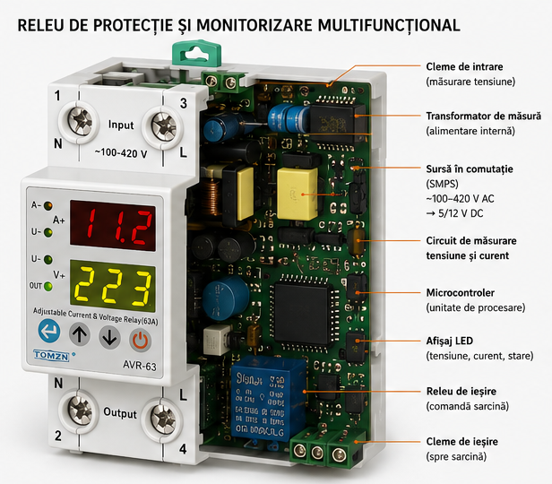
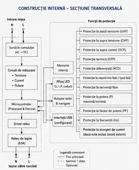
In residential settings, the dominant form today is no longer the single-function relay, but the multifunction protection and monitoring relay (Fig. 0 and Fig. 4): a 1–2 DIN-unit module that integrates all the functions described above into the same body.
Purpose and role in the installation: it continuously monitors the voltage, the current and (on three-phase models) the phase balance, compares the measured values with adjustable thresholds and, when exceeded, commands disconnection of the load through an output contact (typically up to 40–63 A) — directly or through a contactor. In practice it replaces a row of separate relays (voltage + phases + thermal) with a single device that:
- Measures U, I, P and the power factor continuously — and displays them on the front LED
- Protects against under/overvoltage (UVP/OVP), thermal overload (OTP), phase loss and wrong sequence, minimum/maximum power and leakage current (with an external toroid: signalling or disconnection through a contactor — it does not replace the 30 mA RCD required by Art. 4.1.5.2.1)
- Delays reconnection after the return to parameters (it protects compressors and pumps from premature restarts)
- Logs the events and, on models with USB/Modbus, reports them to the automation system
The cost of a numeric relay with Modbus communication (50–150 EUR) is justified for houses with photovoltaic systems, backup generators or complex technical installations.
Normative reference
In I7-2011 relays appear in two roles. As protective devices: Art. 4.3.1.2 lists, among the devices for protection against overcurrents, „overload protection relays (thermal relays, circuit breakers, overcurrent protection relays, fuses)”. For motors, Art. 5.3.1.7.2 requires protection against abnormal heating „for every motor whose rated power is greater than 0.5 kW”, and Art. 5.3.1.7.2.1 spells it out: „The protection of three-phase motors is achieved with a current-dependent device, with time delay, which monitors all three phases, set to at most the rated current of the motor.” Protection against voltage loss (Art. 5.3.1.7.3) and against wrong phase sequence (Art. 5.3.1.7.6) is required conditionally — wherever its absence „can produce a dangerous condition, damage to the machine”; for lifts, Art. 7.18.1 refers to the manufacturer’s technical instructions. As a means of functional switching, the relay appears in Art. 5.3.4.5.3.2 b):
„[…] functional switching may be achieved by means of switches, semiconductor devices, contactors, relays, plugs and socket-outlets of rated current not exceeding 16 A."— I7-2011, Art. 5.3.4.5.3.2 b)
For motors, this usually means that the relay drives the coil of a contactor — the scheme in the box above. Panel-mounted multifunction relays can also switch directly, through their own contact, but only loads within the utilisation category of that contact (the 40–63 A rating is usually given for AC-1, resistive load); motors and compressors are switched through a contactor. The product standards for protection relays are from the IEC 60255 series, and voltage relays for generators and photovoltaic installations additionally comply with the grid-connection requirements (EN 50549). Corrected on 11 September 2026: the normative section wrongly claimed that I7 does not treat relays as protective devices and leaned on two articles cited outside their scope, and the ElectroSchema box promised functions that do not exist in the app.
ElectroSchema
In the visual consumer unit in ElectroSchema, the voltage relay and the protection relay (configured as an MCB, RCCB or RCBO) are placed on the DIN rails as EPD-type equipment. For the voltage relay, the properties panel sets the Umin/Umax thresholds, the reconnection delay and the number of poles. Both are included in the bill of materials (BOM); they are not yet drawn in the electrical schematics.
Discussion
Comments are moderated before publication. Your email is not displayed publicly.